|
System 2000 has been designed to the highest standards of safety and reliability.
Our design criteria satisfy the most demanding health and safety regimes in the
world today. The following significant innovations are unique in chain hoist controllers.
Expansion Capabilities

System 2000 is further enhanced by two ground-breaking expansion possibilities.
Firstly, there is an exciting new development allowing analogue load cell outputs
to be connected directly to the back of the controller. The exact weight on each
motor point can then be displayed on a real time chart via any Windows application.
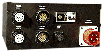
A laptop or PC is connected via a standard serial port on the rear of the controller
(see pic above).
The second new capability is full motion control using standard CM encoders,
allowing precise movement of hoists to cue sequences. This system may be controlled
from the same laptop as the load cells, with both programs running concurrently.
All this fits into a 5u 19” box and requires no extra power above the standard
32A required for an 8-way controller.
Electrical Protection
All controllers are protected by a 30mA RCCD, type C 3 phase MCB for each motor
channel and a type B single phase MCB for the low voltage control circuit. This
comprehensive protection complies with all major international electrical regulations.
Voltage Selection
System 2000 is designed to be operated in any country with mains 3 phase voltages
varying from 120 to 415 volts between phases. No adjustment is necessary
provided the hoists have been set to the local voltage. This feature makes System
2000 safe from overvoltage abuse - the most common cause of damage to controllers.
Phase reversal
Phase reversal is achieved via the 32A reversing plug supplied with each unit,
ensuring that all motors are in phase with each other and preventing accidental
“wrong way” movement which can occur with individual channel reversing.
LED display
Each channel on the local and remote controllers is equipped with a bi-colour
LED which displays red or green, depending on direction selected. This reduces
the amount of information displayed, providing a clear and easily interpreted
reading of the status.
The E Stop information is displayed by yellow LEDs, reducing any confusion
with the directional red and green LEDs on each channel. Only when an E Stop is
activated will the yellow LED light up, allowing easy tracing of the active stop.
Additionally, the front panel has three neons to indicate three correct phases
connected and a 24V LED to indicate control power present.
Reliability
System 2000 is constructed with minimal PCB’s and new generation relays, which
can be replaced in seconds, yet will not be dislodged (even if you do drop the
flight case off the ramp!). Every component has been selected with rugged touring
duty in mind, and simplicity of operation and replacement in the unlikely event
it should ever prove necessary
|

